DualShock4 Reverse Engineering - Part 4
In case you missed previous episodes:
- Part 1 where you can read about this DualShock 4 totally messed up that I’m trying to repair
- Part 2 where I figure out which commands can be sent via USB and dump the flash
- Part 3 where I play with test commands, DFU mode and list all supported GET commands
Welcome to Part 4! ![]()
As said at the end of Part 3, there is a leaked reverse-engineered code available online. Enough with blackbox reverse-engineering, we can start now a pseudo white-box analysis by reading the code.
The quality could be better, this file is probably the copy-paste of what you get when you open the binary in a decompiler. To those not used to decompilers: no, it cannot be recompiled, its not even close to a valid C file.
Anyway, a good text editor is enough to dig into that 45000-lines file and understand a bit about the behavior of the DS4.
Looking at the strings
When I start to look at a new binary, the first thing I do is looking for
interesting strings, 10/10 low hanging fruits. ![]()
In this binary there are lots of printf() and lots of strings, this makes me
think that there should be a way to debug using a serial port.
Anyway, this one below seems the version of this firmware.
Compiled on Aug 3 2013, way older than the one running in my controller.
char aCopyrightC2012SonyComput[64] = "Copyright(C) 2012 Sony Computer Entertainment Inc.              ";
version_info_t stru_8040 = {
  { 'A', 'u', 'g', ' ', ' ', '3', ' ', '2', '0', '1', '3', '\0', '\0', '\0', '\0', '\0' },
  "07:01:12", 256, 12544, 3, 73, 5, 229376
};
And few lines below, there is something that seems a command line interface:
char aTeppouMonitorVer1_0[70] = "\r\nTEPPOU Monitor Ver 1.00\r\n (C) 2013 Sony Computer Entertainment Inc.";
char aCopyrightC2013SonyComput[74] = "Copyright(C) 2013 Sony Computer Entertainment Inc. All rights reserved.\r\n";
struc_7 dbg_cmds[40] =
{
  { "INFO",                   0x9E63 },
  { "db",                     0xA255 },
  { "dh",                     0xA255 },
  { "dw",                     0xA255 },
  { "sb",                     0xA30B },
  { (const char *)0x31678,    0xA30B },
  { "sw",                     0xA30B },
  { "extI2c",                 0xA73F },
  { "sysI2c",                 0x16C35 },
  { "spiAcc",                 0xC7E5 },
  { "spiBmi055",              0xD0F1 },
  { "jediLed",                0x14C73 },
  { "mtr",                    0x151D7 },
  { "iEep",                   0x155CF },
  { "adc",                    0xF7D9 },
  { "fLock",                  0x15A91 },
  { "audio",                  0x10797 },
  { "btenable",               0x183B9 },
  { "btdisable",              0x183BF },
  { "btshowladdr",            0x183C5 },
  { "btwladdr",               0x183CB },
  { "btunpair",               0x183D1 },
  { "btshowreg",              0x183D7 },
  { "btshowdevinfo",          0x183DD },
  { "btpost",                 0x183E3 },
  { "btshowtask",             0x183E9 },
  { "btshowsema",             0x183EF },
  { "btshowstack",            0x183F5 },
  { "btsniff",                0x183FB },
  { "btexitsniff",            0x18401 },
  { "bat",                    0xE16D },
  { "tc7710",                 0xEFAF },
  { "factory",                0x165D1 },
  { "pwr",                    0x99B3 },
  { "flash",                  0x9E9D },
  { "sbcDec",                 0x117F1 },
  { "sbcEnc",                 0x118B1 },
  { "tp",                     0xC40D },
  { "auth",                   0x20DDD },
  { (const char *)0x316F7,    &dword_0 }
};
Just brainstorming: maybe also JDM-055 has test pins? My friend with the good
electronic lab is on vacation, so I’ll go down this path in future.
Let me know if you ever heard of this interface on a DS4! ![]()
Anyway, let’s not get distracted and go back to repairing the DS4.
Oh wait.
void dbg_wait_password()
{
  int v0; // r3
  char v5; // [sp+4h] [bp-2Ch]
  memcpy32(&v5, (int *)"~~ REDACTED, A RANDOM PASSWORD HERE ~~", 0x18u, v0);
  /* ... */
}

void debug_task()
{
  signed int v0; // r0
  dbg_wait_password();
  dbg_print_welcome();
  while ( 1 )
  {
    do
    {
      printf("\r\n>:");
      dbg_get_args(dbg_cmdline, &dbg_argc, (char **)dbg_argv);
    }
    while ( dbg_argc <= 0 );
    v0 = dbg_get_cmd_idx((const char *)dbg_argv[0]);
    if ( v0 < 0 )
      printf("\r\nIllegal Command.\r\n");
    else
      dbg_cmds[v0].func(dbg_argc, (char **)dbg_argv);
  }
}
LOL
We can spend days just by looking at all the functionalities in this binary,
but let’s go back to the main task: make my DS4 work again. ![]()
IMU Calibration
This C file has just few functions with a meaningful name, all the others
are named sub_xxxx() where xxxx is the address of the function.
Speaking of USB HID reports, void usb_hid_get_report(int a1); and
void usb_hid_set_report(signed int a1, unsigned int a2, int a3);
immediately caught my attention.
Both functions have a huge switch-case inside, where part of it is compiled as
a binary search using if/else, this is why you will see below sometimes case
2 and sometimes else if (a1 == 123)
We should start from somewhere, so.. let’s have a look about the implementation
of GET 0x02 (Get Calibration Data):
void usb_hid_get_report(int a1) {
/* ... */
case 2:
usb0_ep0_send_buf[0] = 2;
*(_WORD *)&usb0_ep0_send_buf[1] = *(_WORD *)&flash_4000_mirror[514];
*(_WORD *)&usb0_ep0_send_buf[3] = *(_WORD *)&flash_4000_mirror[516];
*(_WORD *)&usb0_ep0_send_buf[5] = *(_WORD *)&flash_4000_mirror[518];
*(_WORD *)&usb0_ep0_send_buf[7] = *(_WORD *)&flash_4000_mirror[520];
/* .... omitted for clarity .... */
*(_WORD *)&usb0_ep0_send_buf[29] = *(_WORD *)&flash_4000_mirror[544];
*(_WORD *)&usb0_ep0_send_buf[31] = *(_WORD *)&flash_4000_mirror[540];
*(_WORD *)&usb0_ep0_send_buf[33] = *(_WORD *)&flash_4000_mirror[546];
*(_WORD *)&usb0_ep0_send_buf[35] = *(_WORD *)&flash_4000_mirror[548];
usb0_ep0_send_buf_len = 37;
usb0_ep0_send_buf_ptr = (int)usb0_ep0_send_buf;
break;
/* ... */
}
Well, seems pretty easy: it sets the first output byte to 0x02,
so that the output message becomes a response to GET 0x02 and then copies
some values from the memory to the USB output buffer.
Now, I don’t know what flash_4000_mirror means, it was named in this way by
the anonymous reverser that published that file. But, given that name, I can think of these things:
- There is a flash memory in the DS4
- It is mapped to 0x4000
- It’s mirrored in RAM, like that at some point you call
flush()and in that moment is written permanently - The IMU calibration data in memory start at position
514(which in HEX is 0x202)
Let’s see where are the calibration bytes in the memory dump obtained in Part 2:
$ hexdump -Cv dump_official.bin
00000000  91 4a 00 00 00 00 4e 81  8e 75 a9 2a 01 00 00 b4  |.J....N..u.*....|
[...]
000001f0  00 00 00 00 00 00 00 00  00 00 00 00 00 00 00 00  |................|
00000200  00 00 ff ff 00 00 05 00  90 22 81 22 98 22 6b dd  |........."."."k.|
00000210  85 dd 77 dd 1c 02 1c 02  19 1e 3e 20 3c 21 c3 de  |..w.......> <!..|
00000220  b8 df 47 e1 05 00 00 00  00 00 00 00 00 00 00 00  |..G.............|
00000230  00 00 00 00 00 00 00 00  00 00 00 00 00 00 00 00  |................|
00000240  00 00 00 00 00 00 00 00  00 00 00 00 00 00 00 00  |................|
00000250  00 00 00 00 00 00 00 00  00 00 00 00 00 00 00 00  |................|
00000260  00 00 00 00 00 00 00 00  00 00 00 00 00 00 00 00  |................|
[...]
They start exactly at 0x202. ![]()
Perfect, so flash_4000_mirror is what has been zeroed out in my broken controller.
Ok, can we change the calibration in some way? Let’s see where else is used
flash_4000_mirror[514].
void usb_hid_set_report(signed int a1, unsigned int a2, int a3) {
  /* ... */
  case 4:
    *(_WORD *)&flash_4000_mirror[514] = *(_WORD *)((char *)&dword_0 + a3 + 1);
    *(_WORD *)&flash_4000_mirror[516] = *(_WORD *)((char *)&dword_0 + a3 + 3);
    *(_WORD *)&flash_4000_mirror[518] = *(_WORD *)((char *)&off_4 + a3 + 1);
    *(_WORD *)&flash_4000_mirror[520] = *(_WORD *)((char *)&off_4 + a3 + 3);
    /* Omitted for clarity */
    *(_WORD *)&flash_4000_mirror[544] = *(_WORD *)((char *)&off_1C + a3 + 1);
    *(_WORD *)&flash_4000_mirror[540] = *(_WORD *)((char *)&off_1C + a3 + 3);
    *(_WORD *)&flash_4000_mirror[546] = *(_WORD *)((char *)&off_20 + a3 + 1);
    *(_WORD *)&flash_4000_mirror[548] = *(_WORD *)((char *)&off_20 + a3 + 3);
    flash_4000_mirror[512] |= 3u;
    flash_mirror_flush();
    break;
  /* ... */
}
Oh nice! ![]() Way easier than I thought! So
Way easier than I thought! So SET 0x04 changes the calibration data.
I have a working DS4 that can be used to obtain valid calibration data:
ffff0000050090226bdd812285dd982277dd1c021c02ab1f55e04320bddffb1f06e00500
It’s not perfect, I know, this is a calibration for another DS4, but it’s way better than all zeros.
Let’s try if SET 0x04 works, by adding this code in jedi_tool.py:
import binascii
# [...]

new_calib="ffff0000050090226bdd812285dd982277dd1c021c02ab1f55e04320bddffb1f06e00500"
           ffff0000050090226bdd812285dd982277dd1c021c02ab1f55e04320bddffb1f06e00500

# Print the calibration before
dump_req(0x02, 41)

# Try to change IMU calibration
hid_set_report(dev, 0x04, binascii.unhexlify(new_calib))

# Print the new calibration
dump_req(0x02, 41)
And cross the fingers! ![]()
$ python3 jedi_tool.py
RID:0x02 data: 000000000000000000000000000000000000000000000000000000000000000000000000
RID:0x02 data: ffff0000050090226bdd812285dd982277dd1c021c02ab1f55e04320bddffb1f06e00500
Seems working, OMG! ![]()
Test the fix
In Part 1 I described the bug found in the hid-sony driver. I added a
workaround to my driver to prevent the crash. The workaround prints a message
on dmesg if the calibration is zero and changes the denominator to 1.
When my broken DS4 is connected, this is what usually happens:
[...] usb 1-2: new full-speed USB device number 3 using xhci_hcd
[...] usb 1-2: New USB device found, idVendor=054c, idProduct=09cc, bcdDevice= 1.00
[...] usb 1-2: New USB device strings: Mfr=1, Product=2, SerialNumber=0
[...] usb 1-2: Product: Wireless Controller
[...] usb 1-2: Manufacturer: Sony Interactive Entertainment
[...] sony 0003:054C:09CC.0082: Invalid calibration data for axis (3), disabling calibration.
[...] sony 0003:054C:09CC.0082: Invalid calibration data for axis (4), disabling calibration.
[...] sony 0003:054C:09CC.0082: Invalid calibration data for axis (5), disabling calibration.
[...] sony 0003:054C:09CC.0082: Invalid calibration data for axis (0), disabling calibration.
[...] sony 0003:054C:09CC.0082: Invalid calibration data for axis (1), disabling calibration.
[...] sony 0003:054C:09CC.0082: Invalid calibration data for axis (2), disabling calibration.
[...] input: Sony Interactive Entertainment Wireless Controller Touchpad as [...]
[...] input: Sony Interactive Entertainment Wireless Controller Motion Sensors as [...]
[...] input: Sony Interactive Entertainment Wireless Controller as [...]
You can see all the lines with Invalid calibration data that are emitted
because the IMU calibration is zeroed-out.
Well, after calling SET 0x04 and setting the calibration data,
this is what happens when the DS4 is reconnected:
[...] usb 1-2: new full-speed USB device number 4 using xhci_hcd
[...] usb 1-2: New USB device found, idVendor=054c, idProduct=09cc, bcdDevice= 1.00
[...] usb 1-2: New USB device strings: Mfr=1, Product=2, SerialNumber=0
[...] usb 1-2: Product: Wireless Controller
[...] usb 1-2: Manufacturer: Sony Interactive Entertainment
[...] input: Sony Interactive Entertainment Wireless Controller Touchpad as [...]
[...] input: Sony Interactive Entertainment Wireless Controller Motion Sensors as [...]
[...] input: Sony Interactive Entertainment Wireless Controller as [...]
No more Invalid calibration data ![]() which means that the calibration is
loaded correctly by the driver.
which means that the calibration is
loaded correctly by the driver. ![]()
A call to GET 0x02 confirms that the calibration stays there even after a reboot:
$ python3 jedi_tool.py
RID:0x02 data: ffff0000050090226bdd812285dd982277dd1c021c02ab1f55e04320bddffb1f06e00500
Ohh yes. The Dualshock4 IMU is now calibrated. ![]()
Side effect of SET 0x04
SET 0x04 does another thing though: it executes this instruction:
flash_4000_mirror[512] |= 3u;
which enables two flags to the word just before the calibration data.
I’m still not sure about the meaning, searching for mirror[512] does not
produce interesting results, it seems not used anywhere except for the GET
0x10 which returns the values of flash[512,513] and flash[256,257].
void usb_hid_get_report(int a1) {
  /* ... */
  case 16:
    usb0_ep0_send_buf[0] = 16;
    *(_WORD *)&usb0_ep0_send_buf[1] = *(_WORD *)&flash_4000_mirror[512];
    *(_WORD *)&usb0_ep0_send_buf[3] = *(_WORD *)&flash_4000_mirror[256];
    usb0_ep0_send_buf_len = 5;
    usb0_ep0_send_buf_ptr = (int)usb0_ep0_send_buf;
  /* ... */
}
Maybe the controller keeps track of the recalibration happened using SET 0x04?
I bet the meaning in the original firmware is this: ![]()
flash->flags |= FLAG_SOMEONE_MESSED_UP | FLAG_EXPIRE_WARRANTY;
Bluetooth MAC
Another issue about this DS4 is the Bluetooth MAC Address wiped out.
The output of GET 0x81 (Get BT Addr) is: 000000000000.
Again, let’s go back in usb_hid_get_report() and search for 129 (0x81):
void usb_hid_get_report(int a1) {
  /* ... */
  if ( v1 == 129 )
  {
    sub_15C5A(usb0_ep0_send_buf);
    usb0_ep0_send_buf[0] = -127;
    usb0_ep0_send_buf_len = 7;
    usb0_ep0_send_buf_ptr = (int)usb0_ep0_send_buf;
    goto LABEL_34;
  }
  goto def_17406;
  /* ... */
}
Ok, it does not directly copy the MAC address, but passes the buffer to
sub_15C5A().
Hello sub_15C5A(), nice to meet you:
_BYTE *sub_15C5A(_BYTE *result)
{
  result[1] = flash_4000_mirror[1818];
  result[2] = flash_4000_mirror[1819];
  result[3] = flash_4000_mirror[1820];
  result[4] = flash_4000_mirror[1821];
  result[5] = flash_4000_mirror[1822];
  result[6] = flash_4000_mirror[1823];
  return result;
}
So the MAC address is located at flash[1818]. As we did before, let’s see who
else uses this and hopefully one result will be related to
usb_hid_set_report(): ![]()
void usb_hid_set_report(signed int a1, unsigned int a2, int a3) {
  /* ... */
  else if ( a1 == 128 )
  {
    flash_4000_mirror[1818] = *((_BYTE *)&dword_0 + a3 + 1);
    flash_4000_mirror[1819] = *((_BYTE *)&dword_0 + a3 + 2);
    flash_4000_mirror[1820] = *((_BYTE *)&dword_0 + a3 + 3);
    flash_4000_mirror[1821] = *((_BYTE *)&off_4 + a3);
    flash_4000_mirror[1822] = *((_BYTE *)&off_4 + a3 + 1);
    flash_4000_mirror[1823] = *((_BYTE *)&off_4 + a3 + 2);
    flash_4000_mirror[1824] = 0;
    flash_4000_mirror[1825] = 0;
    flash_mirror_flush();
  }
  /* ... */
}
Bingo! So SET 0x80 (128) updates the device MAC address. Let’s try to
change it to one similar to the working DS4:
dump_req(0x81, 8)
dump_req(0x12, 15)

print("Change MAC to 28:51:65:11:ae:a0")
hid_set_report(dev, 0x80, b'\x28\x51\x65\x11\xae\xa0')

dump_req(0x81, 8)
dump_req(0x12, 15)
Output:
RID:0x81 data: 000000000000
RID:0x12 data: 000000000000082500000000000000
Change MAC to 28:51:65:11:ae:a0
RID:0x81 data: 28516511aea0
RID:0x12 data: 28516511aea0082500000000000000
Yeess!! ![]()
![]()
![]() MAC Address changed!
MAC Address changed!

Flash Diff
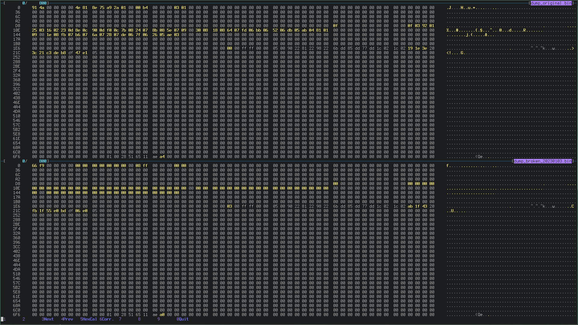
Now, let’s inspect the differences between the flash of the broken DS4 and the working one. Above the working DS4, below the broken one:

The flash memory of the broken one is getting better.
There is still a lot of work to do, for example:
- Huge chunk of bytes that is all zero at lines D8, 10E and 144
- Some bytes still at 0 also in the first line.
- Line 1E6 has a
03caused by theSET 0x04, but at the moment does not seem a problem
It is curious that the IMU calibration written in flash differ in some bytes
from the other flash, even though appears correct if read using GET 0x02.
An unknown request
Another interesting request is SET 0x85, which takes 6 bytes and stores them
starting at flash[6].
The same data can be read using GET 0x86. I don’t know what is the content.
It is used only by SET 0xa0 11 2 where puts that somewhere else (maybe the
USB output buffer?), haven’t had time to investigate yet.
void sub_15C08(int a1)
{
  unsigned int v1; // r1
  v1 = 0;
  do
  {
    flash_4000_mirror[v1 + 6] = *(_BYTE *)(a1 + v1 + 1);
    ++v1;
  }
  while ( v1 < 6 );
  flash_mirror_flush();
}

void usb_hid_set_report(signed int a1, unsigned int a2, int a3) {
  /* ... */
  case 133:
    sub_15C08(a3);
    break;
  /* ... */
}
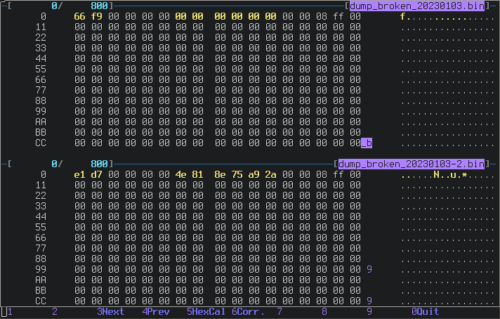
Anyway, my working DS4 has this value 4e818e75a92a so I cloned it into the
broken controller.
Diff of the flash contents before and after SET 0x85:

Checksum
At this point it’s quite clear that the first two bytes of the flash are a checksum of the contents, and the source confirms my hypothesis:
void flash_mirror_flush_internal()
{
  // ...
  *(_WORD *)flash_4000_mirror = flash_mirror_calc_checksum();
  // ...
}
Cool! And how is this checksum used?
void flash_mirror_load()
{
  /* ... */

  if ( flash_mirror_calc_checksum() == *(unsigned __int16 *)flash_4000_mirror )
  {
    LOBYTE(word_1FFE01E0) = 1; // Everything ok
  }
  else
  {
    LOBYTE(word_1FFE01E0) = 0;
    v3 = flash_4000_mirror;
    LOWORD(v4) = 0;
    do
    {
      *(_DWORD *)v3 = 0;
      v3 += 4;
      v4 = (unsigned __int16)(v4 + 1);
    }
    while ( v4 < 0x200 ); // The magic loop
  }
  /* ... */
}
Oh nice, if the checksum is not valid, there is a loop that clears out the flash, 4 bytes per iteration, from the beginning to 0x800.
I suspect (but haven’t tried yet) that if the battery of the controller dies while it’s writing on the flash, at the next startup the checksum does not match and the DS4 gets totally messed up like this one.
Flash Mirror
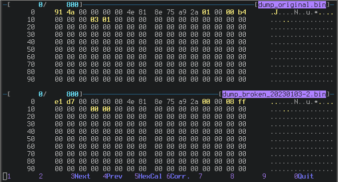
At this point the first line starts being more similar to the working one:

Look at the byte 12, there is a 0x01 in the original DS4 and a 0x00 in the
messed-up one. What is that?
I found out that SET 0xA0 0x0A is the responsible for this, a strange command:
-
SET 0xA0 0x0A 1writes 0x01 atflash[12] -
SET 0xA0 0x0A 2 3e717f89writes 0x00 atflash[12]
Why is so difficult to write 0 there? Is that a passcode or what?
The behavior was unknown to me, until I left the 0x01 there and the DS4
started acting strangely: at every reboot my changes were gone.
So, well, this is the real meaning of “flash mirror”. ![]() 0x01 enables the
mirror in only one direction.
0x01 enables the
mirror in only one direction.
Conclusion
That’s it guys! At least for now :)
The controller is still not working ![]() , but now the broken DS4 has its own
MAC Address and the IMU calibration back in place.
, but now the broken DS4 has its own
MAC Address and the IMU calibration back in place.
There are lots of other features that should be investigated, I’ll continue my research and write a new post in future with other updates.
If you have any knowledge about the DS4 that can help me, please let me know!
![]()
![]()
![]()
Thank you for reading! ![]()
EDIT: Part 5 here
~~~
If you want to get in touch, drop me an email at ds4@the.al or ping me on IRC
(the_al@freenode|libera|hackint) or Discord (the_al).