DualShock4 Reverse Engineering - Part 5: Stick calibration
If you missed previous episodes:
- Part 1 where you can read about this DualShock 4 totally messed up that I’m trying to repair
- Part 2 where I figure out which commands can be sent via USB and dump the flash
- Part 3 where I play with test commands, DFU mode and list all supported GET commands
- Part 4 where we figured out how change MAC address, recalibrate IMUs and understood a bit better how the flash mirror works.
Hello again! ![]()
After publishing Part 4, I received lots of messages from people who helped me with reverse engineering this and I want to say a biig Thank You to all of you!
In particular, Nielk1 gave me lots of extremely useful hints and shown me this wonderful wiki.
Another big thank you goes to mxn who discovered some interesting Enums in the leaked source code that we’ll see in a moment.
In this part I’d like to focus on a set of commands that allow people to recalibrate and center analog sticks and triggers (L2/R2) of their DualShock 4.
But, let’s go in order.
Feature reports
There is a file (/ControllerUpdate_Ver0x004D/HwRawAPI.cs)
in the ZIP uploaded on archive.org (Part 4 for more details) that contains
a beautiful list of HID Feature Requests and parameters used by that tool to
interact with a DualShock 4:
.class ReportIDCode
{
  .field [...] JediRawAPI.ReportIDCode INPUT_REPORT = int32(0x1)
  .field [...] JediRawAPI.ReportIDCode OUTPUT_DEVICE = int32(0x5)
  .field [...] JediRawAPI.ReportIDCode GET_MOTION_CALIB_DATA = int32(0x2)
  .field [...] JediRawAPI.ReportIDCode SET_MOTION_CALIB_DATA = int32(0x4)
  .field [...] JediRawAPI.ReportIDCode SET_FACTORY_COMMAND = int32(0x8)
  .field [...] JediRawAPI.ReportIDCode GET_CALIB_FLAG = int32(0x10)
  .field [...] JediRawAPI.ReportIDCode GET_IEEP_DATA = int32(0x11)
  .field [...] JediRawAPI.ReportIDCode GET_PARING_INFO = int32(0x12)
  .field [...] JediRawAPI.ReportIDCode SET_PARING_INFO = int32(0x13)
  .field [...] JediRawAPI.ReportIDCode SET_USB_BT_CONTROL = int32(0x14)
  .field [...] JediRawAPI.ReportIDCode SET_BDADR = int32(0x80)
  .field [...] JediRawAPI.ReportIDCode GET_BDADR = int32(0x81)
  .field [...] JediRawAPI.ReportIDCode SET_FACTORY_DATA = int32(0x82)
  .field [...] JediRawAPI.ReportIDCode SET_ADR_TO_GET_FACTORY_DATA = int32(0x83)
  .field [...] JediRawAPI.ReportIDCode GET_FACTORY_DATA = int32(0x84)
  .field [...] JediRawAPI.ReportIDCode SET_PCBA_ID = int32(0x85)
  .field [...] JediRawAPI.ReportIDCode GET_PCBA_ID = int32(0x86)
  .field [...] JediRawAPI.ReportIDCode GET_TRACK_RECORD = int32(0x87)
  .field [...] JediRawAPI.ReportIDCode SET_CALIBRATION_COMMAND = int32(0x90)
  .field [...] JediRawAPI.ReportIDCode GET_CALIBRATION_STATE = int32(0x91)
  .field [...] JediRawAPI.ReportIDCode GET_CALIBRATION_RESULT = int32(0x92)
  .field [...] JediRawAPI.ReportIDCode GET_CALIBRATION_DATA = int32(0x93)
  .field [...] JediRawAPI.ReportIDCode SET_TEST_COMMAND = int32(0xa0)
  .field [...] JediRawAPI.ReportIDCode SET_BT_ENABLE = int32(0xa1)
  .field [...] JediRawAPI.ReportIDCode SET_DFU_ENABLE = int32(0xa2)
  .field [...] JediRawAPI.ReportIDCode GET_FIRM_INFO = int32(0xa3)
  .field [...] JediRawAPI.ReportIDCode GET_TEST_DATA = int32(0xa4)
}
Just out of curiosity, in Part 4 I described an “unknown request” (SET 0x85) that writes
6 bytes into the flash which are readable with GET 0x86.
Well, from this enum we see that this request writes the PCBA ID, which
probably is an identifier for the board.
Anyway, in this post I want to focus only on a small subset of them:
SET_CALIBRATION_COMMAND = 0x90
GET_CALIBRATION_STATE   = 0x91
GET_CALIBRATION_RESULT  = 0x92
GET_CALIBRATION_DATA    = 0x93
Analog sticks and their issues
In the DualShock 4 there are two iconic analog sticks, each of them is created
using two potentiometers, one tracks the movements on the X axis and one on
the Y axis. There is also a small button at the bottom that when is pressed
acts as L3 or R3.
This video explains way better than me how do analog sticks work:
So basically, this is an analog stick under the hood:
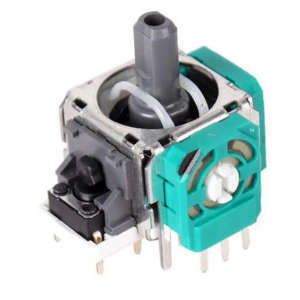
For each axis (X, Y), if the thumbstick is at one end, the potentiometer applies minimum resistance to the electricity flowing through it. If the thumbstick is at the extreme opposite, it applies maximum resistance.
The software of the controller samples every few milliseconds (probably 10ms or so) the voltage using an ADC and, in this way, it knows precisely the position of each stick.
After a long use, the potentiometers may get dirty and the analog sticks starts drifting randomly. So, if you like DIY, you buy a new potentiometer, replace it and… it’s totally not centered or calibrated!
Is there an easy solution to this? I’m glad you asked! ![]()
There is a group of undocumented commands that can recalibrate exactly these data in the DS4:
- Center and Range (Min/Max) of the analog sticks
- Release, Middle, FullStroke points of the L2/R2 triggers
- Motion Sensor values (not investigated in this post)
I’ll explain in this post how does this work and link a Python script that does everything for you.
Calibration commands
The main command is a HID Feature Request SET 0x90, called SET_CALIBRATION_COMMAND, which (thanks to the HwRawApi.cs file) has this syntax:
SET 0x90 [Action] [Device] [Target] [Data1] [Data2]
Each field (Action, Device, …) is 1 Byte.
Where:
-
Actioncan be one of{ None = 255, Start = 1, Stop = 2, Measure = 3 } -
Devicecan be one of{ None = 255, AnalogStick = 1, MotionSensor = 2, TriggerKey = 3 }
Now, if Device is AnalogStick:
-
Targetcan be one of{ None = 255, StickCenter = 1, StickMinMax = 2 } -
Data1andData2are not used
If Device is TriggerKey:
-
Targetcan be one of{ None = 255, TriggerReleasePoint = 1, TriggerMiddlePoint = 2, TriggerFullStrokePoint = 3 } -
Data1indicates which trigger{ L2 = 1, R2 = 2} -
Data2is not used
I didn’t investigate if Device is MotionSensor because I don’t have the gear to calibrate them.
Anyway, in that case, the Target can be one of:
{
	AccelRefXP = 1, AccelRefXM = 2, AccelRefYP = 3,
	AccelRefYM = 4, AccelRefZP = 5, AccelRefZM = 6,
	GyroOffset = 7,
	GyroRefXP = 8, GyroRefXM = 9, GyroRefYP = 10,
	GyroRefYM = 11, GyroRefZP = 12, GyroRefZM = 13,
}
SET 0x90 can start, stop calibration and sample data. There are other GET
requests that can give you some data about the currently running calibration:
GET 0x91 GetCalibState, returns 3 bytes:  deviceId, targetId, stateId
GET 0x92 GetCalibResult, returns 3 bytes: deviceId, targetId, stateId
GET 0x93 GetCalibData, returns N bytes:   deviceId, targetId, numPackets, curPacket, dataLen, [data]
I don’t go deep into them because they do not seem interesting, you can find some use of them in the Python script linked below.
Theoretical steps to perform calibration
After digging a bit into the (reverse engineered) source code of the firmware I figured out the sequence of commands to do the calibration.
Analog sticks: center calibration
Stick center calibration requires these steps:
-
Startcommand, which begins the calibration - One or more
Measurecommand to sample the center of the sticks -
Stopcommand, to complete calibration and save data in the configuration flash
Which in practice becomes like this:
# 1. Start calibration
SET 0x90 1 1 1 # SetCalibration: Start, AnalogStick, StickCenter

# 2. Ensure the stick is in the center

# 3. Sample data, this can be called multiple times
SET 0x90 3 1 1 # SetCalibration: Measure, AnalogStick, StickCenter

# 4. Stop and store calibration
SET 0x90 2 1 1 # SetCalibration: Stop, AnalogStick, StickCenter
Analog sticks: range calibration
Stick min-max calibration instead requires these steps:
-
Startcommand, which begins the calibration - The sensor update loop now stores information about the range of the sticks, so you should move the sticks all around their range
-
Stopcommand saves the data
L2 / R2 triggers
I’m sure there are easier ways to calibrate L2/R2, but after some hours trying commands I found these steps seems working:
-
Startcommand to begin calibration - 6
Samplecommands: {Release, Mid, Full Stroke} for both {L2, R2} -
Stopcommand to store calibration.
Flash diffs
You can see in the image below the differences in the configuration flash before (above) and after (below) centering the analog sticks with my broken DS4:
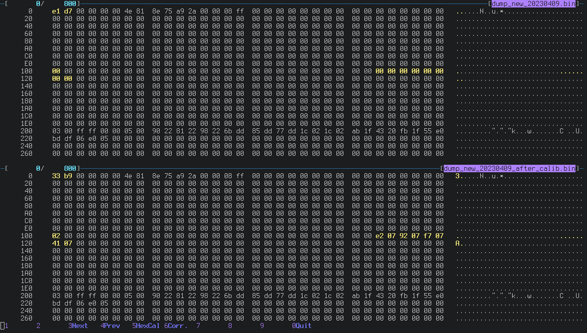
Bytes from 0x11a to 0x122 are the calibration of the two sticks.
What is that 0x02 written at location 0x100?
Calibration Flags
In Part 4 I was joking about two bits set at location 0x200 after rewriting
IMU calibration using SET 0x04.
The content were changed from 0x00 to 0x03.
I bet the meaning in the original firmware is this:
flash->flags |= FLAG_SOMEONE_MESSED_UP | FLAG_EXPIRE_WARRANTY;
Well, thanks to the Enums reported above, it’s easy to figure out the meaning of them: GET 0x10 can be used to read exactly location 0x100 and 0x200.
From the HwRawApi.cs we can see that the name for that Feature Request is:
[...] ReportIDCode GET_CALIB_FLAG = 0x10
And by digging a bit both into that file and in the source, we can find the meaning of each bit:
GET 0x10 GetCalibFlag, returns 4 bytes (two uint16_t)

Byte 0: (0x200 in flash)
    isGyroCalibOk        = 0x01,
    isAccelCalibOk       = 0x02,

Byte 2: (0x100 in flash)
    isStickMinMaxCalibOk = 0x01,
    isStickCenterCalibOk = 0x02,
    isL2CalibOk          = 0x04,
    isR2CalibOk          = 0x08
}
Basically after calling SET 0x04 and rewriting the IMU calibration,
isGyroCalibOk and isAccelCalibOk are set automatically.
Strange enough, these are not set on a new DualShock 4 V2, even if the IMU is
correctly calibrated.
The Python script
Enough with the theory. How do I recenter my DS4?
In this Github repo you can find two scripts:
-
ds4-calibration-tool.pydoes what is described in this post, it has a simple terminal UI. -
ds4-tool.pyis a collection of undocumented commands and allows you to play with (or break) the DS4.
This is a sample execution of ds4-calibration-tool:
$ python3 ds4-calibration-tool.py

*********************************************************
* Welcome to the fantastic DualShock 4 Calibration Tool *
*                                                       *
* This tool may break your controller.                  *
* Use at your own risk. Good luck! <3                   *
*                                                       *
* Version 0.01                            ~ by the_al ~ *
*********************************************************

Waiting for a DualShock 4...
Found a DualShock 4: vendorId=054c productId=09cc
Dualshock4 online!

Choose what you want to calibrate:
1. Analog stick center
2. Analog stick range (min-max)
3. L2 / R2 (beta, let me know if works)
> 1
Starting analog center calibration...
Press S to sample data or W to store calibration (followed by enter)
> S
Press S to sample data or W to store calibration (followed by enter)
> S
Press S to sample data or W to store calibration (followed by enter)
> W
Stick calibration done!!

Here is some debug data from the DS4 about the calibration
Data is split in 4 chunks; we are at 0
Sample 0, data=6e083d0741085807
Sample 1, data=0271083e073f0859
Sample 2, data=076b083d07430858
Sample 3, data=07
The following images are an example of before/after stick center calibration. Look at the differences for Axis 0,1,3,4 when the analog sticks are in the center.
| Before calibration | After calibration |
|---|---|
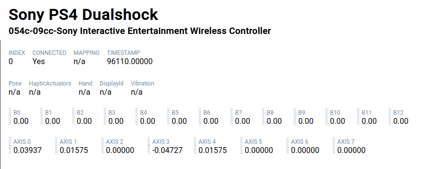 |
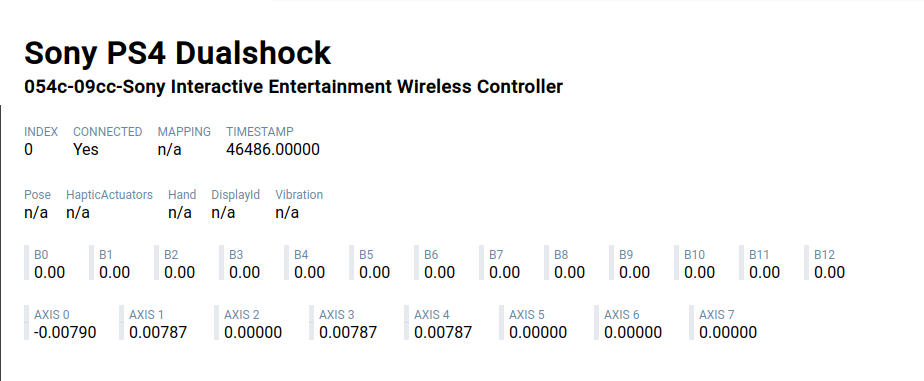 |
Temporary calibration (EDIT: 2023-04-25)
Thanks to Zac who pointed out that all the changes are gone after the DS4 goes into standby.
In Part 4 you can find described the behavior of the flash mirror. By default the changes of configuration are not written in the flash but this can be changed.
On my DS4, for an unknown reason (maybe an updated firmware?), even if the flash mirror is configured as “temporary”, the changes in calibration are permanent.
What to do if all changes are gone after a reboot of the DS4?
Simple: change the behavior of the flash mirror. You can use the ds4-tool.py
available in the same repo.
Some useful commands are:
# Dump the flash to a file
$ ./ds4-tool.py dump-flash filename.bin

# Know if changes are temporary or permanent (0: permanent; 1: temporary)
$ ./ds4-tool.py get-flash-mirror-status

# Change flash mirror behavior (0: permanent; 1: temporary)
$ ./ds4-tool.py set-flash-mirror-status 0
In case you change this, I would suggest to revert the flash mirror state back as temporary after the calibration is complete.
Conclusion
I hope these new discoveries and tools can be used to give new life to old and broken DS4, let me know if this helped you in some way!
While I was writing this post, I was also playing with undocumented commands
(not even listed in the source code from 2013!), and well…
I managed to brick reboot permanently my DS4 into an undocumented mode ![]() .
.
I’ll write soon Part 6 describing this strange mode and asking for help again ![]() .
.
Thank you for reading! ![]()
~~~
If you want to get in touch, drop me an email at ds4@the.al or ping me on IRC
(the_al@freenode|libera|hackint) or Discord (the_al).